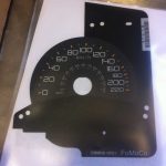
MITSUBISHI PAJERO AM REMOTE
SUITS
| Series / Badge | Build date from | To |
| NM Badges GLS | 06/2000 | 10/2002 |
| NP (K76T, K77T) Badges GLX-R | 06/2002 | 2008 |
Frequency 315 Mhz
Aftermarket Remote. Opens doors remotely (can be self programmed or locksmith)
See our homepage for Car Key Specialists in your area
If in South East Queensland, we can do it for you, call 0401212147 for details.
Programming Instructions For Remote On
2000 TO 2008
Remote Programming
Official Procedure
All remotes are deleted when programming, so make sure to re program any existing remotes at the same time.
- Ensure Ignition is switched OFF, and doors are closed.
- Place a Jumper wire between PIN 1 and PIN 4on the OBD2 connector. This is “Grounding” PIN 1.

- With the Jumper in place, press and release the HAZARD LIGHT Button 6 times
- The doors will LOCK and UNLOCK, or the indicator lights will flash to confirm learning mode.
- Press and release the LOCKbutton on the 1st remote to be programmed.
- Within 10 seconds press and release the LOCKbutton on the same remote twice.
- The doors will LOCK and UNLOCK, or the indicator lights will flash to confirm successful programming.
- For any additional remotes, immediately repeat steps 3 – 5 with the next remote.
NOTE: IF YOU CANNOT GET YOUR CAR INTO PROGRAMMING MODE PLEASE SEEK PROFESSIONAL HELP FROM A LOCKSMITH OR LOCAL KEY SPECIALIST
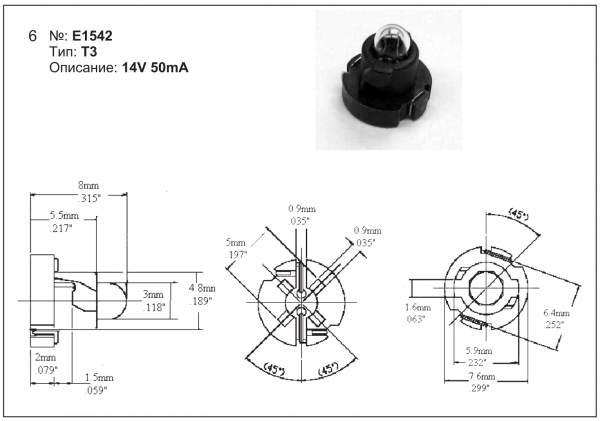
The dash globes are as follows
T3
not too sure where it fits
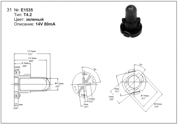
T4
T4.2 –
Flush mount globe usually fitted to hard circuit board, always the globe you don’t have as the globe is not replaceable easily with out the plastic base.
fitted to Toyota’s clocks Ford falcon clocks and instrument clusters as a back light

T5. Normally replaceable
DIAGNOSTIC CHARTS – V6 Engines,
ABS DIAGNOSTIC TROUBLE CODE TABLE
DTC CODE DESCRIPTION
12 No Fault
21 Front Right Wheel Speed Sensor Incorrect Signal
23 Front Right Wheel Speed Sensor Short Circuit or Open Circuit
25 Front Left Wheel Speed Sensor Incorrect Signal
27 Front Left Wheel Speed Sensor Short Circuit or Open Circuit
28 Wheel Speed Sensor Frequency Error
31 Rear Right Wheel Speed Sensor Incorrect Signal
33 Rear Right Wheel Speed Sensor Short Circuit or Open Circuit
35 Rear Left Wheel Speed Sensor Incorrect Signal
37 Rear Left Wheel Speed Sensor Short Circuit or Open Circuit
41 Front Right Inlet Valve Solenoid Fault
42 Front Right Outlet Valve Solenoid Fault
45 Front Left Inlet Valve Solenoid Fault
46 Front Left Outlet Valve Solenoid Fault
55 Rear Axle Inlet Valve Solenoid Fault
56 Rear Axle Outlet Valve Solenoid Fault
61 Pump Motor or Relay Fault
63 Valve Solenoid Relay Circuit Fault
67 Stop Lamp Switch Circuit Fault
71 Control Module Internal Fault
85 System Voltage Too Low
DIAGNOSTIC CHARTS – GEN III V8 Engine, V8 – WITH THROTTLE RELAXER
ABS/TCS DIAGNOSTIC TROUBLE CODE TABLE
DTC CODE DESCRIPTION
12 No Fault
21 Front Right Wheel Speed Sensor Incorrect Signal
23 Front Right Wheel Speed Sensor Short Circuit or Open Circuit
25 Front Left Wheel Speed Sensor Incorrect Signal
27 Front Left Wheel Speed Sensor Short Circuit or Open Circuit
28 Wheel Speed Sensor Frequency Error
31 Rear Right Wheel Speed Sensor Incorrect Signal
33 Rear Right Wheel Speed Sensor Short Circuit or Open Circuit
35 Rear Left Wheel Speed Sensor Incorrect Signal
37 Rear Left Wheel Speed Sensor Short Circuit or Open Circuit
41 Front Right Inlet Valve Solenoid Fault
42 Front Right Outlet Valve Solenoid Fault
45 Front Left Inlet Valve Solenoid Fault
46 Front Left Outlet Valve Solenoid Fault
47 Priming Valve Solenoid Fault
48 Switching Valve Solenoid Fault
51 Rear Right Inlet Valve Solenoid Fault
52 Rear Right Outlet Valve Solenoid Fault
55 Rear Left Inlet Valve Solenoid Fault
56 Rear Left Outlet Valve Solenoid Fault
58 Throttle Relaxer PWM (Pulse Width Modulation) Interface Fault
61 Pump Motor or Relay Fault
62 RPM Signal Fault (refer diagnostic charts in both the V6 and GEN III V8 Sections
63 Valve Solenoid Relay Circuit Fault
64 Throttle Relaxer Control Module Position Fault
65 Throttle Relaxer Motor Fault
66 Throttle Relaxer Control Fault
67 Stop Lamp Switch Circuit Fault
68 TPS (Throttle Position Sensor) Monitoring Fault
71 Control Module Internal Fault
72 Serial Data Fault (refer diagnostic charts in both the V6 and GEN III V8 Sections)
73 Spark Retard Monitoring Fault (refer diagnostic charts in both the V6 and GEN III V8 Sections)
73 Requested Torque Circuit Fault – V6 Engines Only
74 Actual Torque Circuit Fault – V6 Engines Only
78 Incorrect Option Coding
85 System Voltage Too Low

alyways annoyed that you cant find the info on how to test this stuff people never post in plain english
so heres what i know
P154A (battery sensor internal failure) stored. In this case, the battery sensor has an internal failure and must be replaced.
here is the test steps
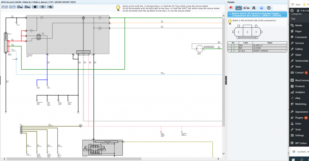
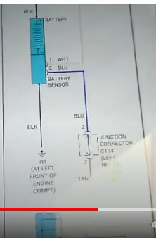
pin 1 blue = lin bus square wave
pin 2 red = battery voltage
pin 3 green = faint ground signal
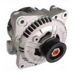
yellow at alternator same as blue wire
SENSOR NOW WORKS WHEN THE HEAD LIGHTS ARE TURNED ON ONLY
THE BATTERY VOLTAGE IS NOW AT 14.3V
ELD VALUE IS 213.5 AMPS
BATTERY CURRENT SENSOR IS 15.7AMPS
WHEN HEAD LIGHTS ARE TURNED OFF THE BATTERY VOLTAGE GOES DOWN TO 12.3VOLTS NO OTHER WAY TO GET VOLTAGE UP
TST DRIVE VEHICLE TO CHECK ALTERNATOR VOLTAGE OUTPUT
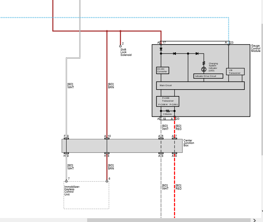
WIRING DIAGRAM
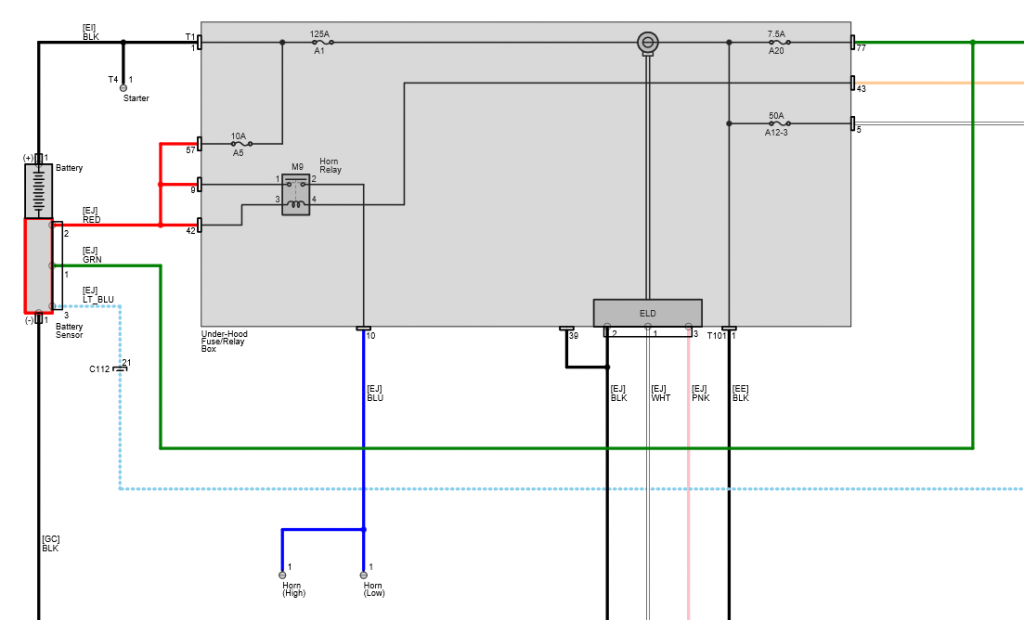
both square waves will be the same
if not the same wiring issue
if the same alternator is not charging then the alternator is no good.
if the alternator is charging and the signals the same the sensor is no good.
Wiring on the sensor its self
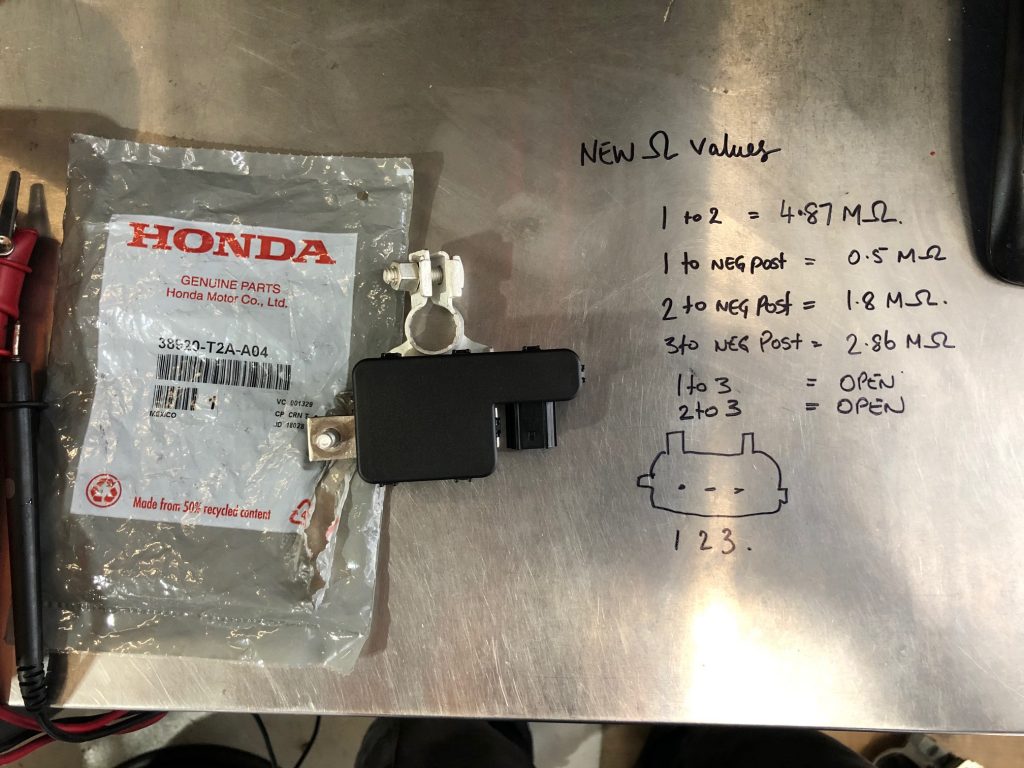
Honda battery sensor – resistance testing with sensor out of car – this was not correct for my vehicle unless the plug is up side down (we are in Australia)
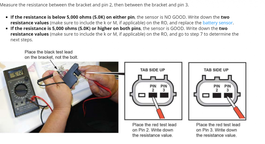
i have 2.75M ohms on both pin 1 and pin2 ??????????????????????
After all that here is what I have measured when I bit the bullet and bought a new one

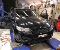
Ford Falcon body control modules FG1 & FG2
A vehicle came in this week and BCM replaced with new unit supplied from ford, a local locksmith had carried out key programming and parameter reset, got the vehicle started (cool)
Post starting the vehicle, the vehicle locks did not work correctly and the BCM configuration thought it was a 4wd and a wagon ( no way)
1. the door ajar switch is open when door closed and closed when door open.
so the BCM is wired differently or opposite in the FG2 Compared with the FG1